Drum punching automatic production monitoring device (2)
Text / Jia Jiazhen
(4) Contact detection method
For the correct positioning of the working part, the contact type detection method shown in FIG. 16 can be used. Only when the working piece is correctly positioned at the predetermined position, the push rod contacts with the regular limit switch, and the line is turned on. For larger work pieces, several contacts can be used.

Fig. 17 is a contact type detection method used in a continuous die, which is used in a continuous die for punching, cutting, and bending. The press is actuated only when the normally open limit switch A is turned on. The line is switched on when it is sent to the active feeder. If, after the last punching, the part was stuck in the mold for some reason and it was not pushed out, then when the second punching, often the limit switch B is cut off by the ejector and the slider will stay at the top dead point. move. If the punch punch is broken and the punch cannot be punched, the pin is pushed up, the limit switch C is cut off, and the slider is also stopped.
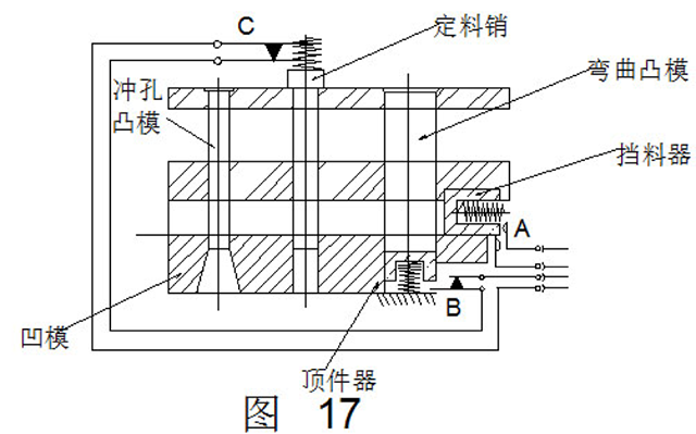
FIG. 18 is a detection method for a punch ejector device. In normal operation, there is a gap of not less than d between the top plate and the sensor, and the line does not pass. If the work piece fails to be ejected, one more piece is punched out next time, and the top plate contacts the sensor and turns on the line.
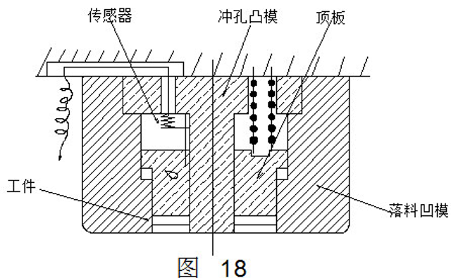
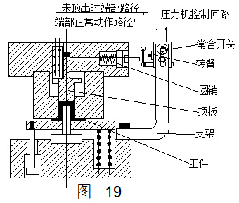
Fig. 19 is a detection method for a tensile member ejecting device. When the stretching piece is normally pushed out, the end part of the top plate leaves a gap, so that the round pin moves to the left. When the upper mold rises, the right end of the round pin does not come into contact with the arm and the press works as usual. If the workpiece is stuck in the die, the top plate is blocked from being pushed out by the spring, and the round pin cannot be reset. When the work piece is lifted up, it touches the turning arm to cut off the regular line.
7, hopper full load detection
As shown in Fig. 20, the pieces fall into the hopper and gradually increase from the bottom to the position of the sensor. When the full-load state touch sensor is reached, an input signal is sent to the control device and the press is stopped.
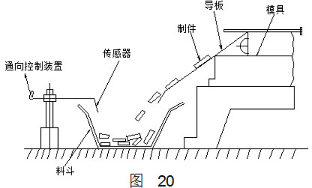
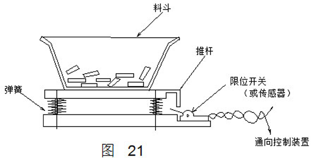
Fig. 21 also shows full load detection. It is equipped with a spring under the hopper. Under the increasing weight of the workpiece, the limit switch is turned on.
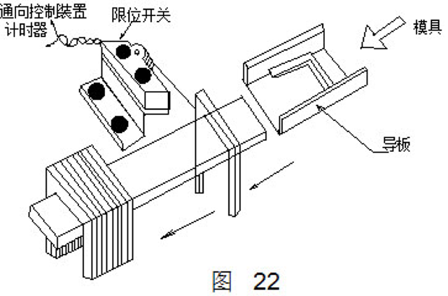
In addition, in the case where the articles are stored neatly in the hopper, each passing article may be used in accordance with FIG. 22 to perform the detection by moving closer to each other. When the workpiece reaches full load, the timer connected to the limit switch operates to alarm for a predetermined amount of time and stop the press.
Second, photoelectric detection device
The characteristic of the photodiode is that its internal resistance is large when it is shielded from light, and its resistance value becomes smaller when the light is irradiated. Therefore, the light signal can be converted into an electrical signal by means of a photodiode. The photoelectric detection device is widely used in automated stamping production due to its easy adjustment, strong shock resistance, and sensitive and reliable work.
Figure 23 shows the photoelectric detection device used in the automatic feeding system for simple CNC punch strips to detect the feeding and withdrawal of strips. After the material is washed out, the waste is withdrawn and the new material is fed. When the new material is sent to the first positioning point, it stops and the stopped signal is sent by the photoelectric device installed at the first positioning point. Therefore, the photoelectric device plays the role of detecting whether the new material has been fed to the first positioning point. . As can be seen from the figure, when the new material is not delivered to the first positioning point, the steering lever is under the action of the spring, causing the B end to leave the light bulb, when the light directly shines on the photoelectric tube; when the new material is sent to the first At the positioning point, toggle the steering lever so that the B end will cover the light bulb; the light will not shine on the photocell, and the photoelectric device will send a stop pulse signal to the control system to stop the new material.
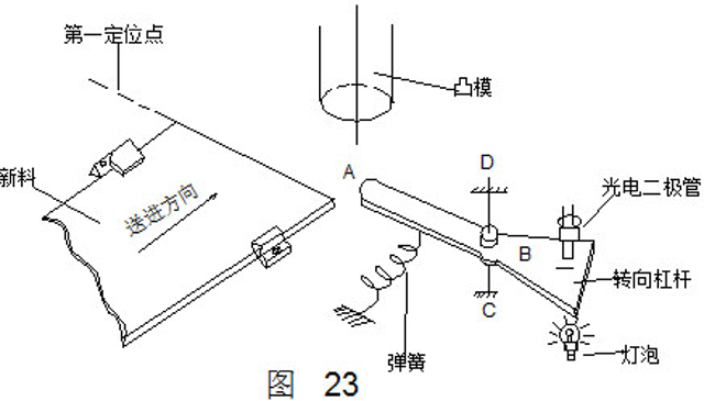
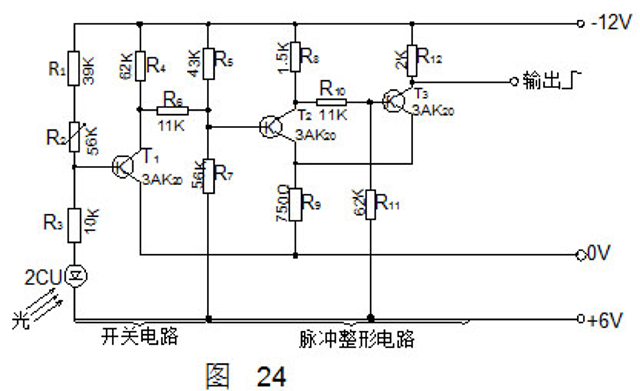
FIG. 24 is a circuit diagram of the above-described photodetection device. The entire line can be divided into two parts. The left side is the transistor switching circuit and the right side is the pulse shaping circuit. Its working principle is as follows: When the new material is not sent to the first positioning point, the B end of the steering lever does not cover the light bulb, and the light shines on the photodiode 2CU. At this time, the resistance value of the 2CU is very small, by R1, R2, The partial voltage of the voltage divider composed of R3 and 2CU causes the base potential Ub1 of the transistor T1 to be greater than OV, the T1 is reliably cut off, and the collector potential UC1 is very low. As a result of the partial pressures of R4, R5, R6, and R7, the base potential Ub2 of the transistor T2 is smaller than 0 V, T2 is turned on, T3 is turned off, and the low potential is output. When the new material is sent to the first positioning point, the B end of the steering lever will cover the light bulb, and the light will not shine on the photodiode 2CU. At this time, the resistance of the 2CU is very large and is divided by R1, R2, R3 and 2CU. As a result, Ub1 of T1 is smaller than OV and T1 is turned on. At this time, Uc1 approaches OV, divides pressure through R5, R7, causes Ub2 to be greater than OV, T2 ends, T8 turns on, the output terminal potential changes from low to high, outputs a positive pulse signal to the control system (stop signal), controls the feeding mechanism Stop feeding.
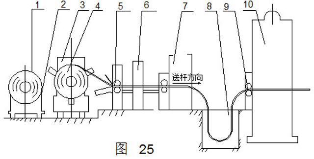
The automatic centering of the unwinding coil and the coordination of the feeding speed between the leveling machine and the feeding mechanism are also realized by means of a photoelectric detection device. In order to explain the working principle of the relevant device, first briefly introduce the function and composition of the unwinding line. The unwinding line is used to roll the material into a blanking press after it has been leveled and punched into a flat blank of the desired shape. Because the roll is uneven, it is necessary to level the roll by more than a dozen leveling mills, and because the feeding mechanism before the blanking press is intermittently moving, the feeding roll before the leveling roll is in continuous motion, so the two are Buffer pits must be used to adjust the feed rate. Considering that the roll head or tail does not meet the requirements for use, a shear bed is placed in the middle of the feeder to cut the head or tail. The main process flow for unwinding is shown in Figure 25. After the roll 1 is conveyed by the carrying trolley 2 into the bilateral uncoiler 3, the opened roll 4 is introduced into the shearing bed 6 through the feeder 5, and the head and tail of uneven thickness and other defects are cut off. The leveling machine 7 continues to enter, enters the buffer pit 8 after the leveling process, and then enters the feeding mechanism 9, and feeds the material into the blanking press 10 through a linkage action with the press. Rough out blanks for drawing or shaping in the next step.
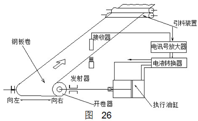
In order to ensure that the coil material is not affected by the tower shape of the coil material, the photoelectric detection device is set between the coiler and the feeder to achieve automatic centering of the coil material. The control principle is shown in Fig. 26. After the light emitted by the transmitter passes through the edge of the steel plate, part of it is blocked, and the unshielded line is received by the photocell. After being amplified by the electric signal amplifier, the signal is transmitted to the electro-hydraulic converter according to the strength of the signal. The pressure oil of different pressure enters the execution cylinder from two loops respectively, and the executive cylinder pushes the decoiler to move left or right so that the steel plate is always located on the center line of the device.
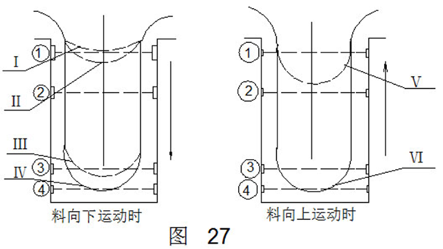
In order to coordinate the feeding speed between the continuous feeding of the leveling machine and the intermittent feeding of the feeding mechanism, a buffer pit is provided between the two. The tape is U-shaped in the buffer pit. The depth of the pit and the sag of the material must be ensured that the high-speed movement will not be delayed due to feeding, and that the material will be straightened between the leveling machine and the feeding mechanism and cause danger, and the feeding mechanism of the press should be prevented. Failure, or the leveling machine feeds too fast, causing the material to fall to the bottom of the pit and be bumped.
According to the above requirements, four groups of photoelectric detection devices and a set of circuits associated with the leveling machine are arranged on the wall of the pit. The design of the action is shown in Figure 27. The material moves downwards. In the first position, due to insufficient material, the automatic feeding mechanism of the press does not move. In the second position, the material continues to fall, and when it falls to the third position, the rapid motor of the leveling machine is cut off. When the speed motor is working, the material will descend in a slow state. When it reaches the fourth position, the leveling machine stops working and it is expected to stop filling in the pit. When the feeding mechanism of the press feeds the material into the press, the material is in the ascending stage, and when it reaches the V position, the leveling machine fast motor is turned on, and continues to feed the material in the pit at high speed.
Third, radiation type detection device
The radioactive isotope 铯90 is a harmless beta ray whose electron velocity is similar to the speed of light. For example, a radioactive source made from 铯90 is placed on one side of a metal plate, and a counter (receiver) is placed on the other side. Due to the local absorption of radiation through the metal, the intensity of the radiation passing through the metal plate is greatly weakened. The thicker the metal plate, the more the radiation is absorbed, the less the counter receives, and the output signal current is correspondingly reduced. In addition, the radiation incident on the metal plate can also produce reflection, and as the distance between the radiation source and the metal plate changes, the reflected beam intensity also changes. These characteristics of the interaction between the ray and the metal plate can be used for the inspection work. For this purpose, the electronic presses connected to the counters and the control circuits for breaking the mechanical movements can automatically operate the press or press according to the different signals output by the counter.
The use of radiation-type detection device can complete the following tasks: 1. Detect the presence and location of the blank is correct; 2. Check the thickness of the blank is in line with the provisions; 3. Check whether the blank is pasted (laminate); 4. Stamping parts count; 5. Synchronization between the press and attached mechanism.
Figure 28 shows a radiometric detection device for different applications. In the figure, a is the blank thickness and lamination on a multi-station automatic press; b in the figure is to check whether the blank orientation is correct; c in the figure is to check whether the workpiece is on the conveyor; d in the figure is tension or relaxation according to the web. The degree automatically adjusts the feeding speed of the web.
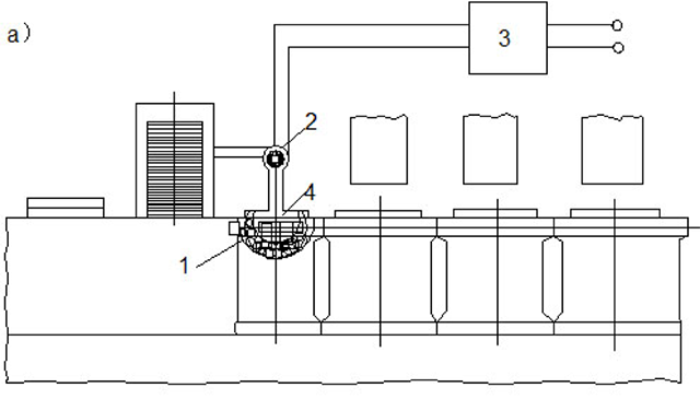
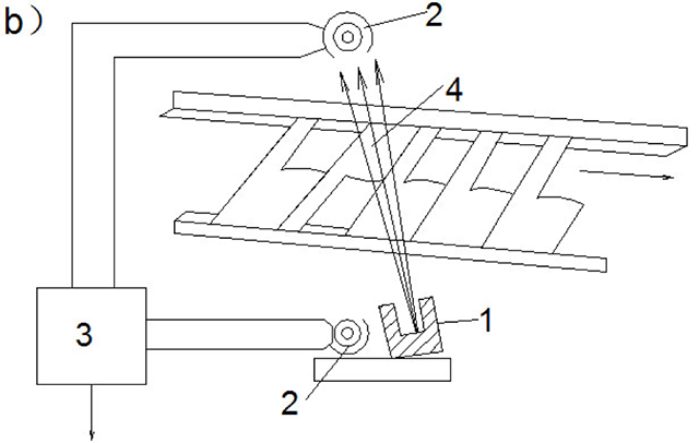
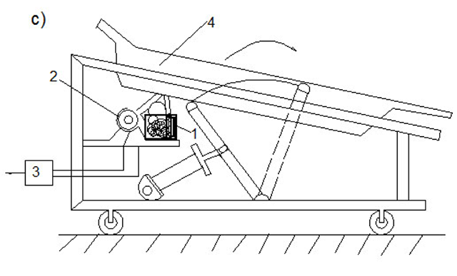
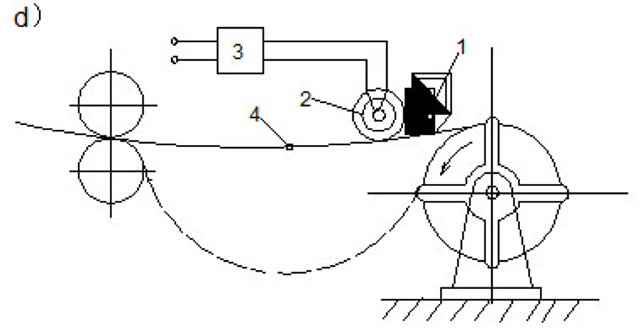
1-radiation source; 2-receiver; 3-electronic relay; 4-blank
Figure 28
ã€Related Links】
Drum punching automatic production monitoring device (1)
Drum punching automatic production monitoring device (2)
Choicy is a Professional Aesthetic Equipment manufacturer producing vacuum rf slimming machine. Also it produces and sells the velashape, vacuum treatment head, RF treatment head, roller RF IR vacuum handle, roller rf ir vacuum handpiece, handle for vacuum rf slimming machine, vacuum rf slimming machine handpiece, etc. Vacuum rf slimming machine adopts vacuum technology and RF technology to achieve massage, body shaping effect. RF vacuum roller machine could replace with the massage manually, and customers feel more comfortable with the treatment. To view the full range of laser machines that we have available, you are welcome to contact us to have a video online meeting to see the machines up close and personal. Also, please send your requirements with a detailed list including the style/item and quantity you require. We will then send our best prices to you. Manufacturers Machine Operation training is included with all machines and no previous experience is required.
Application area
 |
| Vacuum rf slimming machine |
Roller Rf Ir Vacuum Handle,Roller Rf Ir Vacuum Handpiece,Handle For Vacuum Rf Slimming Machine,Vacuum Rf Slimming Machine Handpiece
Choicy , https://www.choicygroup.com